Simple Class AB Amplifier
An audio signal has to drive your speakers with both positive and negative voltages. To accommodate this, a class AB amplifier has two output transistors, one that handles positive voltages, and another that handles negative voltages. The only tricky part is understanding what goes on when the voltage is very close to zero, on its way from positive to negative, or vice versa. More on this later. To begin, we’ll jump right in with the simplest possible implementation of a class AB amplifier, and then start adding features, one step at a time, in order to improve its performance. Here is a simple class AB amplifier:
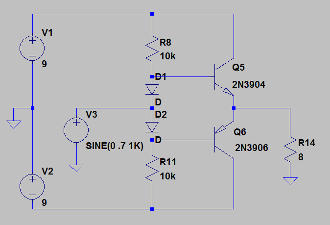
The input is a sine wave with a 700 mV amplitude. The output is a pair of transistors, each of which transmits half of the sine wave. Q5 is an NPN transistor that passes the positive half of the sine wave, while Q6 is a PNP transistor that transmits the negative half. In order for Q5 to turn on, its base has to be raised to approximately 600 mV above ground. Likewise, in order for Q6 to turn on, its base has to be approximately -600 mV relative to ground. The bias network R8-D1-D2-R11 provides the necessary voltages to keep Q5 and Q6 biased slightly into conduction, and depends on the fact that the forward bias voltage across a diode is approximately 600 mV. There is no great coincidence here, of course, since Q5 is just a forward biased diode when probed from base to emitter, while Q6 looks like a forward biased diode when probed from emitter to base. Resistor R14 is sized to stand in for an 8 Ohm speaker load. So far, so good - but wait - when we simulate this circuit using LTSpice, there's no voltage amplification!
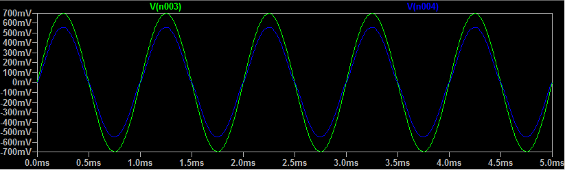
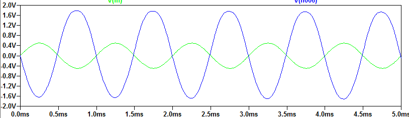
This figure compares the voltage at the input with the voltage at the output. In fact, the output voltage is slightly less than the input. The voltage gain is slightly less than 1. What gives? I started out with this example in order to make a very important point. Voltage gain is often useless unless it also comes with current gain. What's the current gain for this example?
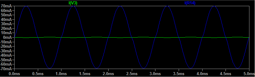
The input current, shown in green, has a peak-to-peak amplitude of approximately 0.9 mA, so that the sinusoidal fluctuations are barely visible on the scale of this image. The output current, shown in blue, however, has a peak-to-peak amplitude of 140 mA when driving an 8 Ohm load, for a current gain of 155. That's a pretty good start - our input signal by itself could not have driven the 8 Ohm speaker load with any appreciable current. But with the current gain that we've just achieved, we could now drive a set of speakers at a modest volume. We're ready to take the next step, which is voltage amplification.
Class AB Voltage and Current Amplifier
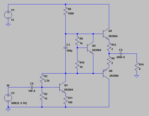
The previous section introduced the simplest possible Class AB amplifier, which turned out to amplify current, but not voltage. In some cases, a current amplifier is exactly what's needed, but for audio applications, we almost always want some voltage amplification as well. So we will now add a modest voltage amplification stage based on a common emitter amplifier. The amplifier is formed from transistor Q1, with emitter resistor R11 and collector resistor R8. The ideal amplification factor is R8/R11 = 1000/ 100 = 10. However, the actual amplification factor, taken from Figure 4, is closer to 5, with the reduction due in part to loading of the amplifier stage by the finite input impedance of the push-pull stage.
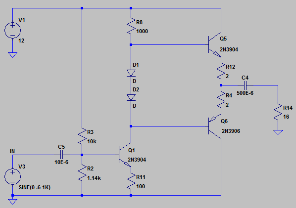
Note a couple of other changes relative to Figure 1: First, there is only a single supply voltage, instead of the positive and negative voltage sources of Figure 1. This is sometimes simpler than dealing with multiple voltage rails, although it comes with its own added complexity. Because the top and bottom voltage rails are at 12 and 0 V respectively, the audio signal at the base of the input amplifier will fluctuate about some nonzero voltage. Your small handheld mp3 player, on the other hand, puts out a voltage that fluctuates about zero. Capacitor C5 enables your zero-biased audio signal to couple to the non-zero biased base of the transistor Q1. How do we enforce a non-zero bias the base of Q1? That's the job of R3 and R2, which provide a voltage bias V1 R2/(R2+R3) at the base of Q1. This works as long as the input impedance of Q1 is large compared to the impedance of R2 in parallel with R3, which is approximately 1 kOhm, not much different than R2 by itself. The input impedance looking into the base of Q1 is approximately the transistor beta ~ 100 x R11 = 10k, which is sufficiently large compared to R2||R3. As before, diode D1 biases the base of NPN transistor Q5 slightly into conduction, while diode D2 biases the base of PNP transistor Q6 slightly into conduction.
Finally, we make a couple of minor modifications that provide some improvement in stability, especially over variations in temperature. First, notice that the bias network for Q1's base is now referenced to Q1's collector. This means that the bias to Q1's base will vary slightly with the signal level. When the input signal to Q1's base is high, Q1's collector current will be also high, dropping lots of voltage across R8, reducing the voltage on the high side of R3, and therefore reducing the bias on Q1, which is the opposite of what the input signal is doing. This is negative feedback and has the effect of stabilizing circuit performance. Likewise, when temperature goes up, the rule of thumb is that the voltage drop from base to emitter decreases by about 2 mV/℃, which increases the amplification factor for the emitter amplifier, increasing the current through Q1, and heating it up even more. Once again, the negative feedback obtained by referencing Q1's bias network to Q1's collector helps to prevent this sort of thermal runaway.
The second change, relative to Fig.XXX, is that we've replaced diodes D1 and D2 with a more complicated looking network, but one that still serves the same purpose of biasing Q5 and Q6 slightly into conduction. It works like this: The voltage drop between Q4's base and emitter is about 600 mV, same as for Q5 and Q6. Mr. Kirchoff requires that this same 600 mV is dropped across R10, which means that there will be 600 mA of current in R10, and roughly the same 600 mA of current in R9 which means, in turn, that there will be about 600 mV voltage drop across R9. So we've just ensured that there will be two diode drops between the bases of Q5 and Q6, which is exactly what we were previously accomplishing with two simple diodes. The virtue of the added complexity is, again, better stability over temperature. When the circuit starts to heat up, the base to emitter voltage drop for Q5 and Q6 will decrease, but so will the base to emitter voltage for Q4, maintaining nearly ideal biasing for Q5 and Q6's bases over a wide range of temperature.
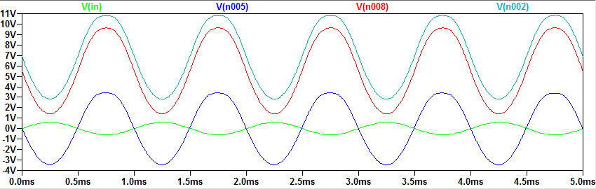
The result, plotted for a single temperature in Fig.XXX, is not much different than the previous case, but is expected to be a bit more stable over temperature fluctuations. This can be important, especially if your circuit is going to be placed in an enclosure where it's likely to heat up by 10 or 20 ℃. The peak voltage is about 1.6 V across an 8 Ohm load, giving an RMS voltage of 1.6/0.707 = 2.26 V and an RMS power of V^2/R = 0.6 W. So we're not exactly going to blow anyone's doors off.
Finally, we have implemented this circuit in Fig.XXX. This simple layout ...
Sample output for the circuit of Fig.XXX is shown in Fig.XXX. A sinusoidal input signal appears in the lower trace, with a peak to peak voltage of just under 200 mV. The output signal is shown in the upper trace with a peak to peak voltage of almost 1 V, for a voltage gain of approximately 5. These data were acquired while the amplifier was fully loaded, driving a set of 8 Ohm speakers.
